
How-To power over your ethernet cable to an access point
by Terry Schmidt
WARNING: Don’t try this unless you have some electric clue. 12v isn’t going to kill you, but you may cause serious damage to your access point and other equipment. Don’t blame me if something goes wrong. I’m not an electrical engineering major, I’m just a networking guy who wanted cheap PoE modules, and decided to write about how I did it. Also there is no set standard (as of 03/19/02) as to which pairs get the positive power, and which pairs get the negative power. Measure your equipment carefully so you don’t damage it.
PoE (Power over Ethernet) Introduction
A number of Access Point manufacturers (Lucent, Symbol) are now offering Power over Ethernet add-on’s for their Access Points. A PoE module inserts DC voltage into the unused wires in a standard ethernet cable (pairs 7-8 and 4-5). The idea is to supply the AP’s power and UTP ethernet connectivity requirements via a single ethernet cable. This works great in areas where you may not have power and/or ethernet easily accessible, like a roof. This also allows you to more easily place the AP closer to the antenna, thus reducing signal loss over antenna cabling. Ethernet signal travels well over CAT 5 cable; 2.4ghz signal doesn’t do as well over antenna cabling. Also ethernet cabling is much cheaper than antenna (LMR-400) cabling. There are currently two types of PoE adapters: a module jack or hub-like device for multiple access points. The following hack creates a simple PoE module pair.

Supplies
| Parts | $ | Tools |
| 2 Port Wall Mount Module | $11 | Multi-meter |
| 1 Port Wall Mount Module | $8 | Wire Cutters or Scissors |
| DC Male Plug | $3 | Electrical Tape |
| DC Female Plug | $1.50 | 110 Punch Tool (Nice but not required) |
| RJ45 Crimpable Plug | 0.50 | RJ45 Crimping Tool |
| Short Ethernet Cable Scrap | $0 | Soldering Iron, Solder |
| Total | $24 |
The 12 volt Apple Airport and the UGate 3300 use a 2.5mm Inner Diameter and 5.5mm Outer Diameter Coax DC Power Jacks. Other Access Points may use different sizes. (Original Linksys WAP11 (5 Volt, 2 Amp) uses 2.1mm Inner Diameter, New Linksys WAP11 uses a 5.5mm Outer Diameter and 2.5mm Inner Diameter) By using less expensive Wall Mount Modules (not CAT5 spec), or not using them at all, you can reduce the parts cost of this project.
Step by Step
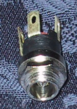
1. Solder wires to the DC Male Power Plug. Solder one pair (2 wires twisted together) to the inner contact connection. This will be the positive power wires. Solder another pair to the outer-contact connection. Notice that on this DC Male Power Plug there are 3 connectors. One is for the center pin, one is for the outer surface, and one goes to the plug housing. You do not need to solder anything to the plug housing connector. This is what it should look liked when finished.
Soldered DC Male Coax Power Plug

New 2 Port Housing Opened
2. Drill a hole in your two-port mount housing. Mount the Male DC plug in the housing.

DC Plug Mounted in 2 Port Housing
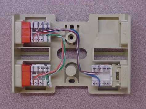
3. Connect the wires in your 2 port jack as follows (also refer to Diagram at bottom of page) (Note: this is the Intel, Symbol, Orinoco Standard, not the Cisco standard for wiring):
| Input Jack | Output Jack | DC Plug | ||
| Pin 1 | <-> | Pin 1 | ||
| Pin 2 | <-> | Pin 2 | ||
| Pin 3 | <-> | Pin 3 | ||
| Pin 4 | <-> | DC Positive Wire 1 | ||
| Pin 5 | <-> | DC Positive Wire 2 | ||
| Pin 6 | <-> | Pin 6 | ||
| Pin 7 | <-> | DC Negative Wire 1 | ||
| Pin 8 | <-> | DC Negative Wire 2 |

Finished 2 Port Wall Mount Jack
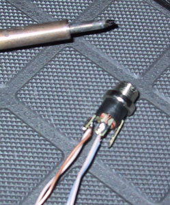
4. Wire the one port wall mount jack as follows:

Left DC Female Plug

Center RJ45 Crimp-able Plug

Right 1 Port Wall Mount Jack Also refer to wiring diagram at bottom of page. (Note this is the Intel, Symbol, Orinoco standard for wiring, not the Cisco standard for wiring)
| Input Jack | Output Jack | DC Plug | ||
| Pin 1 | <-> | Pin 1 | ||
| Pin 2 | <-> | Pin 2 | ||
| Pin 3 | <-> | Pin 3 | ||
| Pin 4 | <-> | DC Positive Wire 1 -> Center Connector | ||
| Pin 5 | <-> | DC Positive Wire 2 -> Center Connector | ||
| Pin 6 | <-> | Pin 6 | ||
| Pin 7 | <-> | DC Negative Wire 1 -> Outer Connector | ||
| Pin 8 | <-> | DC Negative Wire 2 -> Outer Connector |

Finished 1 Port Housing Wiring
5. Plug in and Test

Both Jacks Open and Done.

Both Jacks Closed and Done
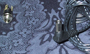
In Use

UGate 3300 and 250′ Feet of Ethernet Cable Using PoE

Apple Airport Guts and 250′ Feet of Ethernet Cable Using PoE
Another PoE Module Setup by Mike Cambell

Using a Lucent 48 vdc phone power supply for the source power. The power supply came as a bundled pack of about 12 that came with the last switch we purchased. It just uses RJ11 to connect to the 4 port doghouse. We use Orinoco AP-1000’s for our infrastructure so we buy the units that come with the PoE splitter. Another credit to making this was the fact that at the time, Lucent only offered the 6 and 12 port injectors. I’ve since noticed that PowerDsine has come up with a single unit. I imagine that Orinoco will be offering those in the future.
— Mike Campbell
Mike Campbell’s PoE injector Module

Lucent 48 VDC phone power supply source that was used for the Orinoco AP-100’s.
Bruce Kozlik’s PoE hub


Uses a Lambda 50 Watt 48VDC supply, Siemon CT coupler and panel. They were able to supply 4 access points, mount it all in a 1 rack unit.

Wiring Diagram (Note: This diagram reflects the Cisco Wiring model (positive power on pairs 7,8, negative power on pairs 4,5). Intel, Symbol, and Orinoco use the opposite (positive power on pairs 4,5, negative power on pairs 7,8) Thanks to Michael Oliver for the wiring diagram.
Testing and Results (Updated 2003 May 05)
The following setup was tested with a UGate 3300 Access Point (Specs 12.0V/0.8A DC) and an Apple Airport Base Station (Specs 12.0V/1.2A DC). They both use the same DC plug.
Power
After having been contacted by many people, my power testing requirements were inadequate (I tested the voltage on an open circuit). I no longer have the PoE modules to test since they have been in a live installation working for 4 months now. How you should test it Measure the voltage across the AP’s DC feed while it’s operating. The DC resistance of Cat5 is about three ohms per hundred feet per conductor, so for 250 foot cable had at least seven (7) ohms resistance. Most of the time the APs draw much less than 0.8A, so you were still above 6V at the AP. In fact, the access points are probably just using linear regulators down to 5V on their insides, so as long as you’re giving them something better than 6V at the terminals they’re likely to work, but at 500 feet they didn’t because the voltage drop was too high once they started turning on. — Scott Carter Regarding problems with long distances and APs that won’t power up properly – You can fix this by using a higher voltage transformer to overcome the voltage drop. Be careful! This is why I said to find the actual power draw of the device. You want to do all your testing using a large power resistor which draws approximately as much power as the device. When you’ve found the correct transformer voltage, double-check your polarity and try it with the device again. The caveat here is that your new transformer rating assumes the resistance that you tested it with. If you find a transformer that works over 500 feet of cable, and you run it over 100 feet, you’ve changed the resistance. Current draw (the device) is the same, but resistance has gone down, so voltage drop goes down. Ergo, the actual voltage reaching the device will go UP, and you might cook something. — From email from “Myself” Recently I did a new Power of Ethernet installation at my loft. I was using the D-Link DWL-900AP+ as the AP on the roof with a about 150 feet of cabiling. The stock transformer is 5 volts 2 amps. Using the online voltage drop calculator, http://www.gweep.net/~sfoskett/tech/poecalc.html, I found that there would be a 3.8 volts voltage drop, and it recommended that I use a 8.8 volt power supply instead. I tried a 9 volt 1.2 amp DC power supply I had sitting around. Intially it looked like it would work, but the AP just kept powercycling every couple of minutes. So I switched to a 12 volt, 1.25 amp DC power supply and it worked great. — Terry
Network Performance
A comparison test was made between using 250′ Feet of Cat 5e Ethernet Cable and PoE, and a 3′ Foot Cat 5 Ethernet Cable with no PoE. This test was done using both the UGate 3300 and Apple Airport Base Station. Ping Times There was no difference in ping times. All were <10ms. Ping Floods Ping flooding was done from a Linux host using the ‘ping -f’ command over a 10/100 switch. The UGate 3300 suffered 8% packet lost under both tests, while the Apple Airport Base Station suffered 1% packet lost under both tests (with and without PoE, and with and without 250′ Feet of Cable). The PoE setup did not affect the amount of lost packets under ping flooding.
Electrical Math
from Ryan Cole
| Wire gauge | Ohms per 1000ft |
| 20 | 10 |
| 22 | 16 |
| 24 | 25 |
| 28 | 65 |
The TIA-568 spec which defines Cat5 (cat 3 as well) specifies that either one shall be no more than 9.38 ohms per 100 meters. Our testing of name brand Cat 5 says more like seven ohms per 100 meters, so 3 ohms per hundred feet is safe and conservative.
— Scott Carter
Ohms Law E = IR (Volts = Amps x Resistance)
We’ll say 22 Gauge wire at 250 Ft under a 1 Amp load
22 Gauge @ 250 Ft = 4 Ohms
E = 1 x 4 or E = 4 Volts
So basically you should expect 4 Volts consumed leaving you 8 volts at the AP end. Let’s do another situation:
28 Gauge over 50 ft at 2 amps
28 Guage @ 50 ft = 3 Ohms
E = 2 x 3 or E = 6 Volts
So in this case you dissipate half your volts. Could be bad, or if I calculate correctly, possibly worse. 6 Volts x 2 Amps = 12 Watts dissipated over the wire 12 Watts / 50 Ft = .24 Watts per foot I would not expect that to start a fire outright, but you could use it to keep your pipes from freezing in the winter. Using 2 pairs as you did in the example will halve the voltage drop — good idea.
Pin Voltage Values
from Bill Cherry
| Vendor/Model | Pins 4 & 5 | Pins 7 & 8 |
| Intel 2011B | +12/24 VDC | -12/24 VDC (1) |
| Symbol 4121 | +12/24 VDC | -12/24 VDC (1) |
| Cisco 350 Pwr Injector | -48 VDC | +48 VDC (2) |
(1) Intel is a re-branded Symbol, these use the Bias T Pwr Injector by Symbol, standard 12 V power supply for up to 100′, 24 V power supply for up to 350′
(2) No Load conditions
Warnings
The 4-5 pair is actually commonly used to carry telephone signals in multi-mode CAT5 wiring, so it’s IMO best avoided. Just in case it’s Monday and your brain hasn’t reached its required level of caffeine yet and you jack in a phone. Especially the exchange will dislike you immensely if you feed it DC. The phone won’t care as long as it’s on hook as it’s isolated by a capacitor to only pick up ringing power (no idea what it does with 48VDC when you pick it up — I think you may just caused potential early death of a cheapo phone 8-).
Example application of multi mode CAT5 (my term, no idea what it’s really called ;-) can be found at http://rswww.com. Follow the path: Cable & Connectors, Networking/Communications, Network Cable & Connector Systems, RS Structured Wiring, RS Data and Telecomm Faceplates. This thing takes ONE (1) CAT5 cable to provide both Ethernet and phone connectivity. I only found this out after I bought it — and to make matters worse, it didn’t follow the Krone colour standard I had everywhere else in the house (duh). Not that it’s hard to work out, but it was a ** pain.
Just one last remark: as the “free” pairs are normally undefined for network use, some manufacturers decided to use them for emission reduction and grounded them in their equipment. Gets a bit ugly if you’ve just kitted out all the sockets with DIY PoE, so best check new stuff before you jack it in. It generally takes only a little adjustment with a sharp knife to correct this ;-). If you’re willing to take a small hit in available power, put a light bulb in series with your feed into the system that is the max your PSU can handle. If it shorts somewhere it’ll light ;-). It’s got a better error recovery mode than a fuse. The posh way of doing this is use one of those electronic fuses that goes high resistance when you have a short — but it won’t tell you it’s doing it and it’s less fun ;-).
A great online voltage drop, dissipation calculator for PoE: http://www.gweep.net/~sfoskett/tech/poecalc.html Multiport PoE injector How-To http://www.knowledgeof.com/index.php/MultiplePortPoeInjector
— Peter Houppermans
One important note that seems to be omitted is the practical maximums for safety.
http://www.powerstream.com/Wire_Size.htm lists an easy to use table. For 24 AWG wire (Standard CAT 5 wiring), the safe maximum is .577 A. Any more at any appreciable enclosed distance (more than 1-2 inches as the scale is already small) presents a heat and fire hazard. Even if there is no fire, the heat generated by such a wire in an enclosed space could potentially soften/melt the insulation such that over a long period of time the insulation becomes compromised and presents an electrocution hazard.
— Gene Cumm
Credits
Matt Peterson of BAWUG for answering all my questions and his web page.

That’s pretty slick Terry.and even on a budjet!..but your’e right if a person is going to go this route… they really need a strong background in basic electonics…at the least! The company I work for (custom sheetmetal shop) is going through growing pains right now! We have aprox. 8 voip phones and 8 nodes, a plotter. 2 printers, and a wireless AP! So now I think it’s time to get rid of the home edition routers,netgear hubs and upgrade. So what is your suggestion to this problem?
Keith
There are several ethernet arduino shields available on different sites, some with poE module and some without poE module .
SO, MY question is if i buy ethernet shield without poE module which is going to cost me less then what is it i am loosing or simply not getting or it it that i ultimately have to buy a poE module and join it with the normal ethernet shield.
Will there be some features not compatible in absence of poE module. Or is it that the ethernet board will not get power via its data cable which is very obvious.And if it is the case then will the ethernet shield without poE MODULE WOULD work normally upon hooking it up with arduino boards like uno or mega.????
Is there any way to calculate/check the power consumption ,current, load etc..
Yes.. There is standard formulas for that.
Factors is Ampere, Volt, cable diameter, cable material (copper) and length.Anyway maximum length of the cable PoE UTP 5cat.
Input Voltage 9 V: < 30 m
Input Voltage 12 V: < 60 m
You're asking for many formulas, please be more detailed.
Thanks lot for rply
how to identify the power consumption ,current ,load. in unit testing
i want to use POE for more than 1 device how can i do this ?
by increasing input voltage and regulator for device.
basically i am sharing internet and i have to set 2 or 3 ethernet switches for users at more distance ..
here is the pic what i want ..